Railway Division

Integrated power supply and protection system (SIAP)

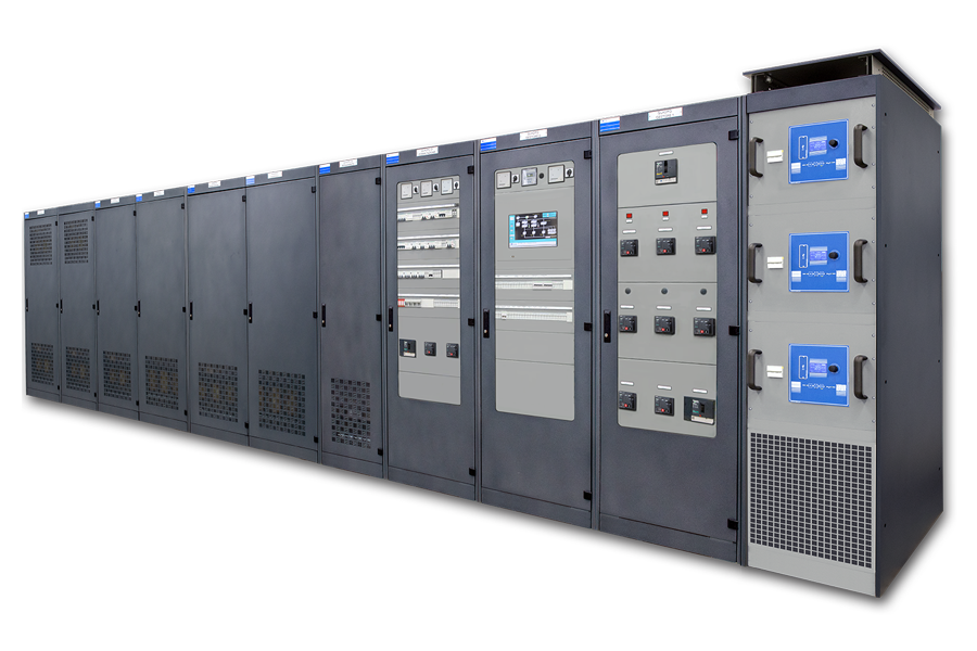
SIAP is not just an ordinary UPS (Uninterruptible Power Supply), but a complete power supply system designed mainly to power railway signalling systems.
SIAP can also be used in any system with similar levels of criticality in terms of application environment and reliability required.
This product is designed for the transformation, regeneration and filtering of normal power from the public distribution network, in order to increase its quality and availability using one or more Uninterruptible Power Supply units and a Power Generator.
From an architectural and functional viewpoint, the entire system has been designed to maximise service availability and continuity. It features high levels of flexibility and modularity: various sizes are available (from 10 kVA to 360 kVA as standard and up to 640 kVA when specifi cally requested) to allow installation of the most efficient configuration based on the client’s energy requirements.
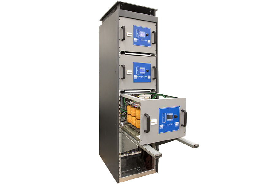
The system comprises various sub-systems, located inside adjacent switchgears that can be accessed with ease for maintenance, with modules fitted on sliding panels to guarantee excellent levels of MTTR (Mean Time To Repair <15 minutes).

Power feeder for signaling and safety systems

The following power feeder features a modular hot-plug construction, a robust construction suitable for heavy-duty uses requiring high levels of reliability. It is the DC part of the SIAP system, and is IS732 D approved.
  • AC/DC converter with output voltage 48Vdc 3kW and 144Vdc 5kW with double insulation.
  • Modular expandable system allowing power expansion to a maximum of n° 7 load-sharing cabinets.
  • High levels of reliability: MTBF > 1 million hours.
  • User interface graphic display.
  • 4 wheels on the underside of the equipment can be used to move it both inside the switchgear, where connection and disconnection operations are carried out on the specific guides, and on the ground.
  • Extended operating range: -25°C +70°C.
  • RS485 modbus type interface.
  • High overload capacity up to 200% for 10 minutes.

SIAP on rail

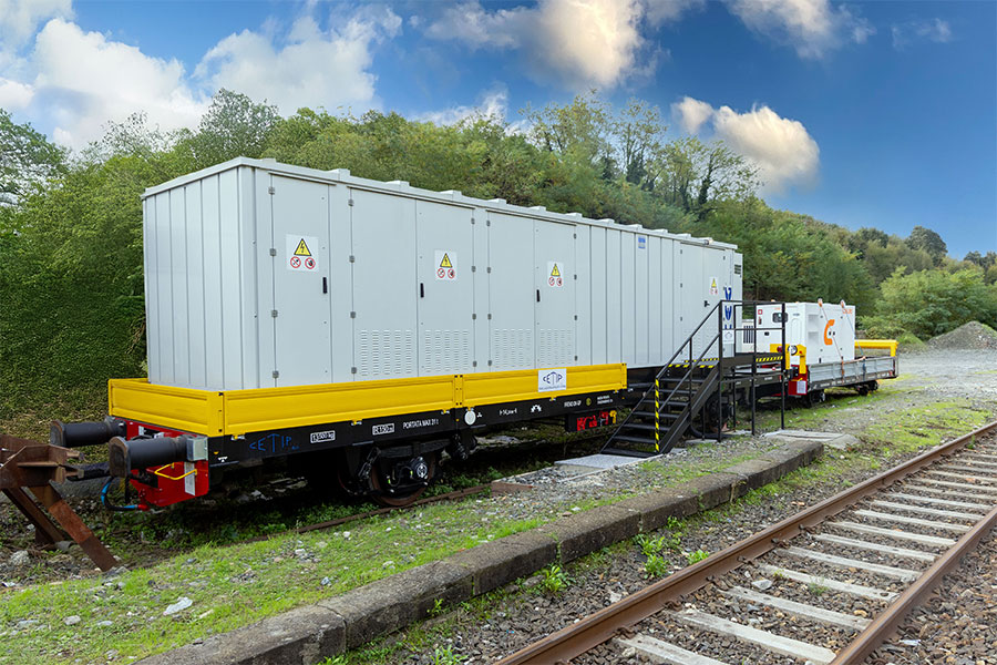
The mobile shelter was born out of the need to manage the transitional period of replacing an old control unit during which a temporary power supply is required to allow sufficient time to decommission the old one and install the new one.
In many cases, given the lack of available premises, the transition period is a difficult problem to solve, which is why it was decided to install an SIAP inside a shelter, which in turn was housed on a railway bogie.
To complete the SIAP, in full compliance with the IS732D standard, there is also the corresponding Generating Set, installed on a second bogie.

DRMI 48 RW

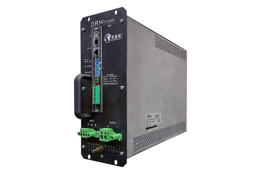
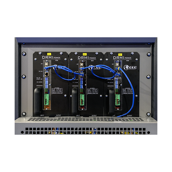
The DRMI-48-RW AC/DC converter is a special power supply designed specifically for the railway market.
The main feature of this power supply is to meet the insulation requirements of the IS732D specification (2.8 kV 50hz and 6 kvp pulse).
In addition to this, it has features particularly appreciated by IS system designers: in particular a high short-circuit current and a hold-up time that allows to connect it to an output UPS without creating voltage gaps during asynchronous switching between inverter and bypass network.
The peculiarities of this product are:
  • Switching power supply for IS applications.
  • 48Vdc AC/DC converter for ACC signalling equipment.
  • Reduction of the overall dimensions and increase of the efficiency while maintaining the insulation characteristics mentioned in the SIAP IS 732D and IS 402 specification.
  • Versions with forced ventilation and natural ventilation.
  • Operating range: -25°C to +70°C.
  • Hot swapping of faulty modules.
  • Active or passive parallel operation.
  • Can be installed in customer's carpentry.

QUALIS

QUALIS: is a pre-configured cabinet for use with DRMI-48-RW converters.
This cabinet can be easily used together with SIAP CEG.
Such a cabinet integrates a modbus communication interface board, input switches and power terminal blocks.
Input connections can be customised as a single input or three separate inputs

drmi 48 rw
drmi 48 rw2

Electrical distribution panels to 1000 Vac for CCS systems

The main innovation made to traditional IS394B-specification systems concerns the ability to self-configure during a fault on the 1000Vac line or on both Step-up switchboard and Step-down switchboard equipment.

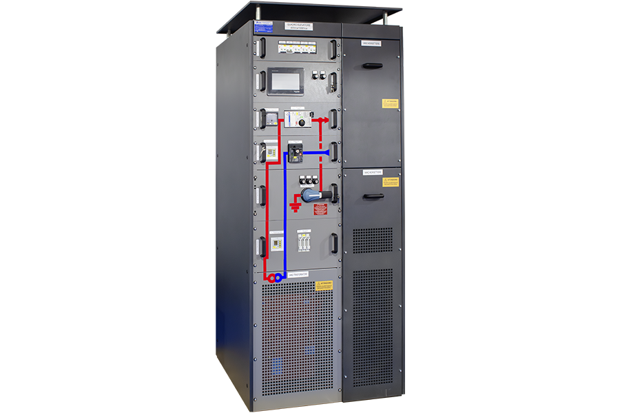
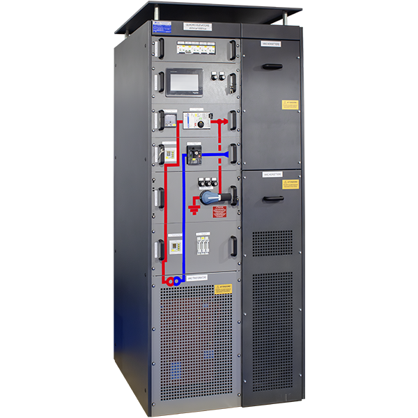
The Step-up switchboard is generally placed in the station and is powered by a no-break source such as an SIAP.
The purpose of such a switchboard is to raise the input voltage from 400Vac to 1000Vac with a transformer at IS365.
The aim is to obtain a power transmission line that has few losses and remains in low voltage LV with the resulting advantages in the use of components and associated costs.

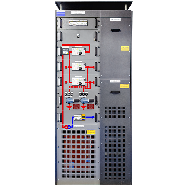
The Step-down switchboard, on the other hand, is placed along the line and has the purpose of converting the 1000Vac line voltage into a voltage that can be used by 'standard' consumers typically 230Vac or 400Vac (single-phase or three-phase) or 150Vac.
This switchboard is essentially composed of a 1000Vac line input/output realised with two motorised isolating switches and a lowering transformer to IS365 specifications.
A section is therefore generally realised with two Step-up switchboard placed at the ends of the line and several Step-down switchboard placed along the line.

The automation of the switchboards is managed by PLC controllers suitable for working in outdoor environments as indicated in IS402.
In the Step-up switchboard there are touch screen monitors with the function of HMI to allow monitoring and management of the section locally, while in the Step-down switchboard there is a management PLC, but without HMI.
These switchboards are connected to each other via an Ethernet ring connection so that an interruption in the network cable (or fibre) does not affect functionality.

In turn, the Step-up switchboard have a dedicated Ethernet communication port for interfacing the system remotely if required.
Generally two servers are provided (for redundancy) to be installed in a central location or in any other place to be chosen by the customer to centralise data from one or more routes. It is then possible to create user workstations to operate on the route.

STEP-UP SWITCHBOARD

quadri elettrici di distribuzione a 1000 vca per gli impianti ccs quadro elevatore

STEP-DOWN SWITCHBOARD

quadri elettrici di distribuzione a 1000 vca per gli impianti ccs quadro abbassatore

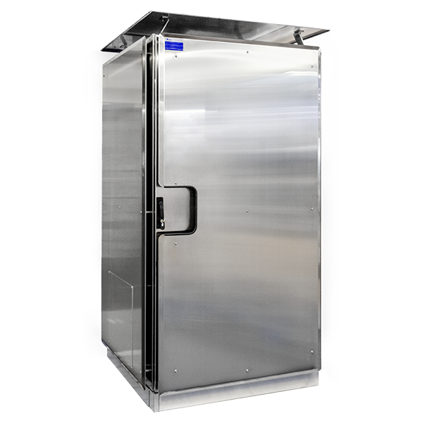
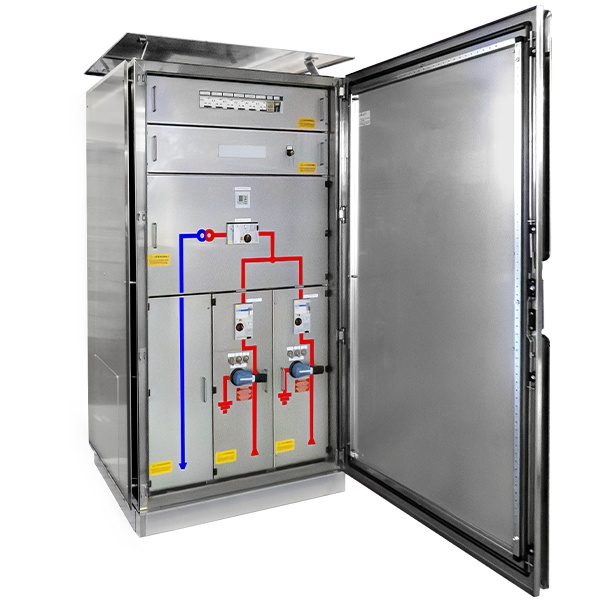
IP55 AISI 304 STAINLESS STEEL OUTDOOR - STEP-DOWN SWITCHBOARD

quadri elettrici di distribuzione a 1000 vca per gli impianti ccs quadro abbassatore da esterno in acciaio inox
quadri elettrici di distribuzione a 1000 vca per gli impianti ccs quadro abbassatore da esterno in acciaio inox2

Static power converters derived from railway overhead line

Power systems with static converters allow the supply of energy in three-phase alternating current at 50Hz to equipment along the line, especially in all those cases where accessibility and / or space available are lacking.
This type of converter, which is usually installed directly on the poles (M or LS) that support the catenary itself, is made in compliance with the technical and construction characteristics in force, and also meets the requirements of the safety and good technique standards.
In particular, these converters have an isolated conversion stage that receives the overhead line voltage at the input, in this case 3.6kVcc, and returns a voltage that can be customized according to the needs, in this case, a 220Vac line and a line at 48Vdc.
The rated power of this product is about 3kW.
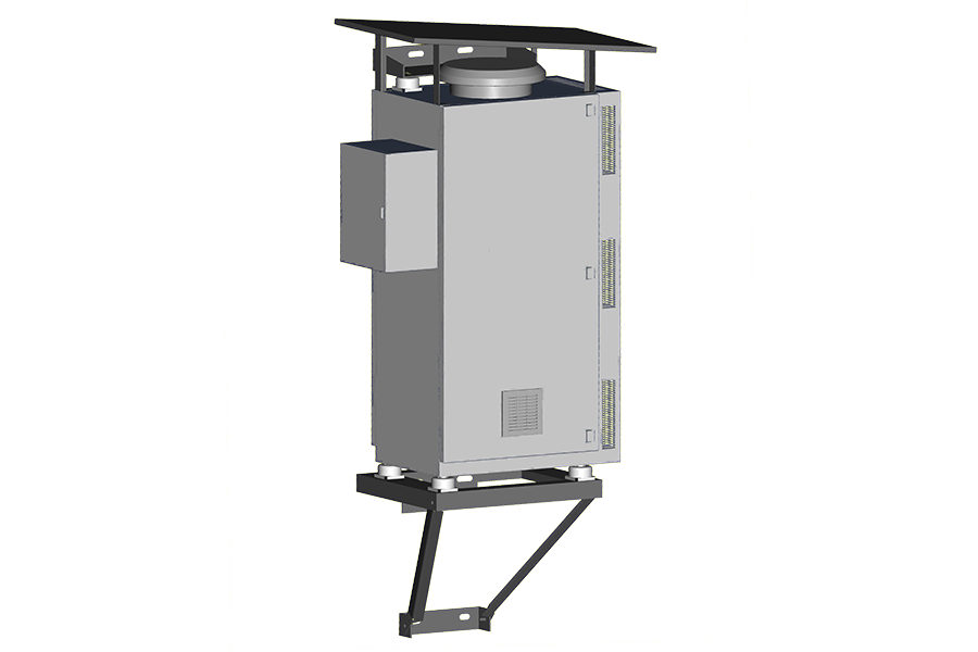
As can be seen from the figure, it is possible to implement various optional technical solutions such as the photovoltaic panel, the additional bank of batteries and the provision for powering from a mobile generator.
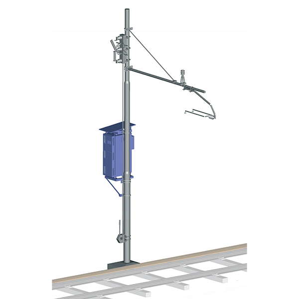
At a mechanical / structural level, the converter is enclosed within a stainless steel cabinet, which is supported by a load-bearing structure that concentrates the weight of the entire system in its lower part.
This part is adequately fixed to the body of the pole on which the converter is installed.
The above cabinet and an example of installation are shown in Fig. 1 and Fig. 2.
An integral part of the converter, even if technically outside the containment cabinet, is the disconnection system, consisting of disconnector, fuse and discharger. In fact, to allow the converter to be connected to the contact line, it is necessary to prepare the intermediate stage consisting of the disconnector.
Furthermore, this disconnector, which has the operation at man's height, it’s needed to allow the switch off of the converter, so as to be able to carry out any maintenance and / or repair work.
convertitori statici di potenza derivati dalla catenaria fig2

From the blog

Latest News & Articles